Reach Us
Mr. C.S Joshi
Director, FARE Labs Pvt Ltd. Gurugram, Haryana.India
Email: csjoshi@farelabs.com
- Conversion of fuel into steam:
Calorific Value is a crucial factor in determining the amount of steam a boiler can generate, as it directly relates to the energy input available for converting water into steam. A higher calorific value means more heat is produced per unit of fuel, potentially leading to more steam generation.
Factors Affecting Steam Generation:
- Calorific Value:
This is the primary factor. Fuels with higher calorific values (like certain types of coal or oil) will produce more heat per unit mass, requiring less fuel for the same steam output.
- Boiler Efficiency:
This refers to how effectively the boiler converts the heat from the fuel into steam. A more efficient boiler will produce more steam from the same amount of fuel.
- Fuel Type:
Different fuels have different calorific values. For example, fuel oils generally have more consistent calorific values than coal, which can vary widely depending on its type and composition.
- Steam Requirements:
The desired temperature, pressure, and flow rate of the steam will affect the amount of fuel needed.
- Boiler Design and Operation:
Factors like the type of boiler, the way it’s operated, and the heat transfer efficiency all play a role in determining how much steam is produced from a given amount of fuel.
Fuel-to-steam efficiency = (Energy output by steam / Energy input by fuel) * 100%
- Energy input by fuel: Fuel consumption * Calorific value of fuel
- Energy output by steam: Steam flow * (Steam enthalpy – Feed water enthalpy)
Q = 540 Kcal is required to convert 1 kg of water to steam.
4. Steam Table:
Steam and temperature possess a reliable relationship whereby if the pressure of the steam is known, its temperature can be predicted (and vice versa). Below is a graph and table of this relationship.
| Saturated Steam – Properties vs. Pressure – Bar | ||||||||||
| Absolute Pressure | Boiling Point | Specific Volume (steam) | Density (steam) | Specific Enthalpy of Liquid Water (sensible heat) | Specific Enthalpy of Steam (total heat) | Latent heat of Vaporization | Specific Heat | |||
| (bar) | (oC) | (m3/kg) | (kg/m3) | (kJ/kg) | (kcal/kg) | (kJ/kg) | (kcal/kg) | (kJ/kg) | (kcal/kg) | (kJ/kgK) |
| 0.02 | 17.51 | 67.006 | 0.015 | 73.45 | 17.54 | 2533.64 | 605.15 | 2460.19 | 587.61 | 1.8644 |
| 0.03 | 24.10 | 45.667 | 0.022 | 101.00 | 24.12 | 2545.64 | 608.02 | 2444.65 | 583.89 | 1.8694 |
| 0.04 | 28.98 | 34.802 | 0.029 | 121.41 | 29.00 | 2554.51 | 610.13 | 2433.10 | 581.14 | 1.8736 |
| 0.05 | 32.90 | 28.194 | 0.035 | 137.77 | 32.91 | 2561.59 | 611.83 | 2423.82 | 578.92 | 1.8774 |
| 0.06 | 36.18 | 23.741 | 0.042 | 151.50 | 36.19 | 2567.51 | 613.24 | 2416.01 | 577.05 | 1.8808 |
| 0.07 | 39.02 | 20.531 | 0.049 | 163.38 | 39.02 | 2572.62 | 614.46 | 2409.24 | 575.44 | 1.8840 |
| 0.08 | 41.53 | 18.105 | 0.055 | 173.87 | 41.53 | 2577.11 | 615.53 | 2403.25 | 574.01 | 1.8871 |
| 0.09 | 43.79 | 16.204 | 0.062 | 183.28 | 43.78 | 2581.14 | 616.49 | 2397.85 | 572.72 | 1.8899 |
| 0.1 | 45.83 | 14.675 | 0.068 | 191.84 | 45.82 | 2584.78 | 617.36 | 2392.94 | 571.54 | 1.8927 |
| 0.2 | 60.09 | 7.650 | 0.131 | 251.46 | 60.06 | 2609.86 | 623.35 | 2358.40 | 563.30 | 1.9156 |
| 0.3 | 69.13 | 5.229 | 0.191 | 289.31 | 69.10 | 2625.43 | 627.07 | 2336.13 | 557.97 | 1.9343 |
| 0.4 | 75.89 | 3.993 | 0.250 | 317.65 | 75.87 | 2636.88 | 629.81 | 2319.23 | 553.94 | 1.9506 |
| 0.5 | 81.35 | 3.240 | 0.309 | 340.57 | 81.34 | 2645.99 | 631.98 | 2305.42 | 550.64 | 1.9654 |
| 0.6 | 85.95 | 2.732 | 0.366 | 359.93 | 85.97 | 2653.57 | 633.79 | 2293.64 | 547.83 | 1.9790 |
| 0.7 | 89.96 | 2.365 | 0.423 | 376.77 | 89.99 | 2660.07 | 635.35 | 2283.30 | 545.36 | 1.9919 |
| 0.8 | 93.51 | 2.087 | 0.479 | 391.73 | 93.56 | 2665.77 | 636.71 | 2274.05 | 543.15 | 2.0040 |
| 0.9 | 96.71 | 1.869 | 0.535 | 405.21 | 96.78 | 2670.85 | 637.92 | 2265.65 | 541.14 | 2.0156 |
| 1 1) | 99.63 | 1.694 | 0.590 | 417.51 | 99.72 | 2675.43 | 639.02 | 2257.92 | 539.30 | 2.0267 |
| 1.1 | 102.32 | 1.549 | 0.645 | 428.84 | 102.43 | 2679.61 | 640.01 | 2250.76 | 537.59 | 2.0373 |
| 1.2 | 104.81 | 1.428 | 0.700 | 439.36 | 104.94 | 2683.44 | 640.93 | 2244.08 | 535.99 | 2.0476 |
| 1.3 | 107.13 | 1.325 | 0.755 | 449.19 | 107.29 | 2686.98 | 641.77 | 2237.79 | 534.49 | 2.0576 |
| 1.4 | 109.32 | 1.236 | 0.809 | 458.42 | 109.49 | 2690.28 | 642.56 | 2231.86 | 533.07 | 2.0673 |
| 1.5 | 111.37 | 1.159 | 0.863 | 467.13 | 111.57 | 2693.36 | 643.30 | 2226.23 | 531.73 | 2.0768 |
| Saturated Steam – Properties vs. Pressure – Bar | ||||||||||
| Absolute Pressure | Boiling Point | Specific Volume (steam) | Density (steam) | Specific Enthalpy of Liquid Water (sensible heat) | Specific Enthalpy of Steam (total heat) | Latent heat of Vaporization | Specific Heat | |||
| (bar) | (oC) | (m3/kg) | (kg/m3) | (kJ/kg) | (kcal/kg) | (kJ/kg) | (kcal/kg) | (kJ/kg) | (kcal/kg) | (kJ/kgK) |
| 1.6 | 113.32 | 1.091 | 0.916 | 475.38 | 113.54 | 2696.25 | 643.99 | 2220.87 | 530.45 | 2.0860 |
| 1.7 | 115.17 | 1.031 | 0.970 | 483.22 | 115.42 | 2698.97 | 644.64 | 2215.75 | 529.22 | 2.0950 |
| 1.8 | 116.93 | 0.977 | 1.023 | 490.70 | 117.20 | 2701.54 | 645.25 | 2210.84 | 528.05 | 2.1037 |
| 1.9 | 118.62 | 0.929 | 1.076 | 497.85 | 118.91 | 2703.98 | 645.83 | 2206.13 | 526.92 | 2.1124 |
| 2 | 120.23 | 0.885 | 1.129 | 504.71 | 120.55 | 2706.29 | 646.39 | 2201.59 | 525.84 | 2.1208 |
| 2.2 | 123.27 | 0.810 | 1.235 | 517.63 | 123.63 | 2710.60 | 647.42 | 2192.98 | 523.78 | 2.1372 |
| 2.4 | 126.09 | 0.746 | 1.340 | 529.64 | 126.50 | 2714.55 | 648.36 | 2184.91 | 521.86 | 2.1531 |
| 2.6 | 128.73 | 0.693 | 1.444 | 540.88 | 129.19 | 2718.17 | 649.22 | 2177.30 | 520.04 | 2.1685 |
| 2.8 | 131.20 | 0.646 | 1.548 | 551.45 | 131.71 | 2721.54 | 650.03 | 2170.08 | 518.32 | 2.1835 |
| 3 | 133.54 | 0.606 | 1.651 | 561.44 | 134.10 | 2724.66 | 650.77 | 2163.22 | 516.68 | 2.1981 |
| 3.5 | 138.87 | 0.524 | 1.908 | 584.28 | 139.55 | 2731.63 | 652.44 | 2147.35 | 512.89 | 2.2331 |
| 4 | 143.63 | 0.462 | 2.163 | 604.68 | 144.43 | 2737.63 | 653.87 | 2132.95 | 509.45 | 2.2664 |
| 4.5 | 147.92 | 0.414 | 2.417 | 623.17 | 148.84 | 2742.88 | 655.13 | 2119.71 | 506.29 | 2.2983 |
| 5 | 151.85 | 0.375 | 2.669 | 640.12 | 152.89 | 2747.54 | 656.24 | 2107.42 | 503.35 | 2.3289 |
| 5.5 | 155.47 | 0.342 | 2.920 | 655.81 | 156.64 | 2751.70 | 657.23 | 2095.90 | 500.60 | 2.3585 |
| 6 | 158.84 | 0.315 | 3.170 | 670.43 | 160.13 | 2755.46 | 658.13 | 2085.03 | 498.00 | 2.3873 |
| 6.5 | 161.99 | 0.292 | 3.419 | 684.14 | 163.40 | 2758.87 | 658.94 | 2074.73 | 495.54 | 2.4152 |
| 7 | 164.96 | 0.273 | 3.667 | 697.07 | 166.49 | 2761.98 | 659.69 | 2064.92 | 493.20 | 2.4424 |
| 7.5 | 167.76 | 0.255 | 3.915 | 709.30 | 169.41 | 2764.84 | 660.37 | 2055.53 | 490.96 | 2.4690 |
| 8 | 170.42 | 0.240 | 4.162 | 720.94 | 172.19 | 2767.46 | 661.00 | 2046.53 | 488.80 | 2.4951 |
| 8.5 | 172.94 | 0.227 | 4.409 | 732.03 | 174.84 | 2769.89 | 661.58 | 2037.86 | 486.73 | 2.5206 |
| 9 | 175.36 | 0.215 | 4.655 | 742.64 | 177.38 | 2772.13 | 662.11 | 2029.49 | 484.74 | 2.5456 |
| 9.5 | 177.67 | 0.204 | 4.901 | 752.82 | 179.81 | 2774.22 | 662.61 | 2021.40 | 482.80 | 2.5702 |
| 10 | 179.88 | 0.194 | 5.147 | 762.60 | 182.14 | 2776.16 | 663.07 | 2013.56 | 480.93 | 2.5944 |
| 11 | 184.06 | 0.177 | 5.638 | 781.11 | 186.57 | 2779.66 | 663.91 | 1998.55 | 477.35 | 2.6418 |
| 12 | 187.96 | 0.163 | 6.127 | 798.42 | 190.70 | 2782.73 | 664.64 | 1984.31 | 473.94 | 2.6878 |
| Saturated Steam – Properties vs. Pressure – Bar | ||||||||||
| Absolute Pressure | Boiling Point | Specific Volume (steam) | Density (steam) | Specific Enthalpy of Liquid Water (sensible heat) | Specific Enthalpy of Steam (total heat) | Latent heat of Vaporization | Specific Heat | |||
| (bar) | (oC) | (m3/kg) | (kg/m3) | (kJ/kg) | (kcal/kg) | (kJ/kg) | (kcal/kg) | (kJ/kg) | (kcal/kg) | (kJ/kgK) |
| 13 | 191.60 | 0.151 | 6.617 | 814.68 | 194.58 | 2785.42 | 665.29 | 1970.73 | 470.70 | 2.7327 |
| 14 | 195.04 | 0.141 | 7.106 | 830.05 | 198.26 | 2787.79 | 665.85 | 1957.73 | 467.60 | 2.7767 |
| 15 | 198.28 | 0.132 | 7.596 | 844.64 | 201.74 | 2789.88 | 666.35 | 1945.24 | 464.61 | 2.8197 |
| 16 | 201.37 | 0.124 | 8.085 | 858.54 | 205.06 | 2791.73 | 666.79 | 1933.19 | 461.74 | 2.8620 |
| 17 | 204.30 | 0.117 | 8.575 | 871.82 | 208.23 | 2793.37 | 667.18 | 1921.55 | 458.95 | 2.9036 |
| 18 | 207.11 | 0.110 | 9.065 | 884.55 | 211.27 | 2794.81 | 667.53 | 1910.27 | 456.26 | 2.9445 |
| 19 | 209.79 | 0.105 | 9.556 | 896.78 | 214.19 | 2796.09 | 667.83 | 1899.31 | 453.64 | 2.9849 |
| 20 | 212.37 | 0.100 | 10.047 | 908.56 | 217.01 | 2797.21 | 668.10 | 1888.65 | 451.10 | 3.0248 |
| 21 | 214.85 | 0.095 | 10.539 | 919.93 | 219.72 | 2798.18 | 668.33 | 1878.25 | 448.61 | 3.0643 |
| 22 | 217.24 | 0.091 | 11.032 | 930.92 | 222.35 | 2799.03 | 668.54 | 1868.11 | 446.19 | 3.1034 |
| 23 | 219.55 | 0.087 | 11.525 | 941.57 | 224.89 | 2799.77 | 668.71 | 1858.20 | 443.82 | 3.1421 |
| 24 | 221.78 | 0.083 | 12.020 | 951.90 | 227.36 | 2800.39 | 668.86 | 1848.49 | 441.50 | 3.1805 |
| 25 | 223.94 | 0.080 | 12.515 | 961.93 | 229.75 | 2800.91 | 668.99 | 1838.98 | 439.23 | 3.2187 |
| 26 | 226.03 | 0.077 | 13.012 | 971.69 | 232.08 | 2801.35 | 669.09 | 1829.66 | 437.01 | 3.2567 |
| 27 | 228.06 | 0.074 | 13.509 | 981.19 | 234.35 | 2801.69 | 669.17 | 1820.50 | 434.82 | 3.2944 |
| 28 | 230.04 | 0.071 | 14.008 | 990.46 | 236.57 | 2801.96 | 669.24 | 1811.50 | 432.67 | 3.3320 |
| 29 | 231.96 | 0.069 | 14.508 | 999.50 | 238.73 | 2802.15 | 669.28 | 1802.65 | 430.56 | 3.3695 |
| 30 | 233.84 | 0.067 | 15.009 | 1008.33 | 240.84 | 2802.27 | 669.31 | 1793.94 | 428.48 | 3.4069 |
1) 1 bar abs = 0 bar gauge = 0.98692 atm = 100 kPa abs = Standard Atmospheric Pressure (IUPAC system)
• Vacuum steam is the general term used for saturated steam at temperatures below 100°C.
• One calorie (kcal) equals 4.184 kJ or 4,184 joules (J).
Example: Boiling Water at 100 °C, 0 bar (100 kPa) Atmospheric Pressure
At atmospheric pressure (0 bar g, absolute 1 bar) water boils at 100 °C and 417.51 kJ of energy is required to heat 1 kg of water from 0 °C to evaporating temperature 100 °C.
Therefore the specific enthalpy of water at 0 bar g (absolute 1 bar) and 100 oC is 417.51 kJ/kg.
Another 2257.92 kJ of energy is required to evaporate 1 kg of water at 100 oC into 1 kg of steam at 100 oC. Therefore at 0 bar g (absolute 1 bar) the specific enthalpy of vaporation is 2257.19 kJ/kg.
The total specific enthalpy for steam at 0 bar gauge is:
hs = (417.51 kJ/kg) + (2257.92 kJ/kg) = 2675.43 kJ/kg = 640.1 kcal/kg
Example: Boiling Water at 170 °C and 7 bar (700 kPa) Atmospheric Pressure
At 7 bar g (absolute 8 bar) the saturation temperature of water is 170.42 °C. More heat energy is required to raise its temperature to saturation point at 7 bar g than needed when the water is at atmospheric pressure. According to the table 720.94 kJ is required to raise 1 kg of water from 0 °C to saturation temperature 170 °C.
The heat energy (enthalpy of evaporation) needed at 7 bar g to vaporize the water to steam is actually less than required at atmospheric pressure. The specific enthalpy of vaporization decreases with steam pressure. The evaporation heat is 2046.53 kJ/kg at 7 bar g.
The specific volume of steam decreases with increased pressure – and the amount of heat energy distributed by the same volume increase. With higher pressure – more energy can be transferred in a steam distribution system.
Example: At atmospheric pressure (10 bar g, absolute 11 bar) water boils at 179.88 °C and 762.6 kJ of energy is required to heat 1 kg of water from 0 °C to evaporating temperature 179.88 °C
Therefore the specific enthalpy of water at 10 bar g (absolute 11 bar) and 179.88 oC is 762.6 kJ/kg.
Another 2013.56 kJ of energy is required to evaporate 1 kg of water at 179.88 °C into 1 kg of steam at 179.88 °C. Therefore at 10 bar g (absolute 11 bar) the specific enthalpy of vaporization is 2013.56 kJ/kg.
The total specific enthalpy for steam at 10 bar gauge is:
hs = (762.6 kJ/kg) + (2013.56 kJ/kg) = 2776.16 kJ/kg = 663.07 kcal/kg
5. Selection of steam pipelines in process plant:
| Sizing of Steam Pipes | ||||||||||||
| Capacity (kg/h) | ||||||||||||
| Gauge Pressure (bar) | Steam Velocity (m/s) | Nominal Pipe Size (mm) | ||||||||||
| 15 | 20 | 25 | 32 | 40 | 50 | 65 | 80 | 100 | 125 | 150 | ||
| Inside Diameter (mm) | ||||||||||||
| 15.8 | 20.9 | 26.6 | 35.0 | 40.9 | 52.5 | 62.7 | 77.9 | 102.3 | 128.2 | 154.1 | ||
| 0.4 | 15 | 9 | 15 | 24 | 42 | 57 | 95 | 135 | 208 | 359 | 564 | 815 |
| 25 | 14 | 25 | 41 | 70 | 96 | 158 | 225 | 347 | 598 | 940 | 1358 | |
| 40 | 23 | 40 | 65 | 112 | 153 | 252 | 360 | 555 | 958 | 1504 | 2173 | |
| 0.5 | 15 | 9 | 16 | 26 | 45 | 61 | 101 | 144 | 222 | 383 | 602 | 869 |
| 25 | 15 | 27 | 43 | 75 | 102 | 168 | 240 | 370 | 638 | 1003 | 1449 | |
| 40 | 24 | 43 | 69 | 120 | 163 | 269 | 384 | 592 | 1021 | 1604 | 2318 | |
| Sizing of Steam Pipes | ||||||||||||
| Capacity (kg/h) | ||||||||||||
| Gauge Pressure (bar) | Steam Velocity (m/s) | Nominal Pipe Size (mm) | ||||||||||
| 15 | 20 | 25 | 32 | 40 | 50 | 65 | 80 | 100 | 125 | 150 | ||
| Inside Diameter (mm) | ||||||||||||
| 15.8 | 20.9 | 26.6 | 35.0 | 40.9 | 52.5 | 62.7 | 77.9 | 102.3 | 128.2 | 154.1 | ||
| 0.7 | 15 | 10 | 18 | 29 | 51 | 69 | 113 | 162 | 250 | 431 | 676 | 977 |
| 25 | 17 | 30 | 49 | 84 | 115 | 189 | 270 | 416 | 718 | 1127 | 1628 | |
| 40 | 27 | 48 | 78 | 135 | 184 | 302 | 431 | 666 | 1148 | 1803 | 2605 | |
| 0.9 | 15 | 11 | 20 | 32 | 56 | 76 | 126 | 179 | 277 | 478 | 750 | 1084 |
| 25 | 19 | 33 | 54 | 93 | 127 | 210 | 299 | 462 | 796 | 1250 | 1806 | |
| 40 | 30 | 53 | 86 | 149 | 204 | 335 | 478 | 738 | 1274 | 2000 | 2890 | |
| 1 | 15 | 12 | 21 | 34 | 59 | 80 | 132 | 188 | 291 | 501 | 787 | 1137 |
| 25 | 20 | 35 | 57 | 98 | 133 | 220 | 314 | 484 | 835 | 1312 | 1895 | |
| 40 | 32 | 56 | 91 | 157 | 214 | 352 | 502 | 775 | 1336 | 2099 | 3032 | |
| 2 | 15 | 17 | 31 | 50 | 86 | 117 | 193 | 275 | 425 | 733 | 1151 | 1663 |
| 25 | 29 | 51 | 83 | 143 | 195 | 322 | 459 | 708 | 1221 | 1918 | 2771 | |
| 40 | 47 | 82 | 133 | 229 | 312 | 515 | 734 | 1133 | 1954 | 3069 | 4434 | |
| 3 | 15 | 23 | 40 | 65 | 113 | 153 | 253 | 361 | 557 | 960 | 1508 | 2178 |
| 25 | 38 | 67 | 109 | 188 | 256 | 421 | 601 | 928 | 1600 | 2513 | 3631 | |
| 40 | 61 | 107 | 174 | 300 | 409 | 674 | 962 | 1485 | 2560 | 4021 | 5809 | |
| 4 | 15 | 28 | 50 | 80 | 139 | 189 | 312 | 445 | 687 | 1185 | 1860 | 2688 |
| 25 | 47 | 83 | 134 | 232 | 316 | 520 | 742 | 1145 | 1974 | 3101 | 4480 | |
| 40 | 75 | 132 | 214 | 371 | 505 | 832 | 1187 | 1832 | 3159 | 4961 | 7168 | |
| 5 | 15 | 34 | 59 | 95 | 165 | 225 | 371 | 529 | 816 | 1407 | 2210 | 3193 |
| 25 | 56 | 98 | 159 | 275 | 375 | 618 | 881 | 1360 | 2345 | 3683 | 5321 | |
| 40 | 90 | 157 | 254 | 440 | 600 | 988 | 1409 | 2176 | 3752 | 5892 | 8514 | |
| 6 | 15 | 39 | 68 | 110 | 191 | 260 | 429 | 611 | 944 | 1628 | 2556 | 3693 |
| 25 | 65 | 114 | 184 | 318 | 434 | 714 | 1019 | 1573 | 2713 | 4260 | 6155 | |
| 40 | 104 | 182 | 294 | 509 | 694 | 1143 | 1630 | 2517 | 4340 | 6816 | 9848 | |
| Sizing of Steam Pipes | ||||||||||||
| Capacity (kg/h) | ||||||||||||
| Gauge Pressure (bar) | Steam Velocity (m/s) | Nominal Pipe Size (mm) | ||||||||||
| 15 | 20 | 25 | 32 | 40 | 50 | 65 | 80 | 100 | 125 | 150 | ||
| Inside Diameter (mm) | ||||||||||||
| 15.8 | 20.9 | 26.6 | 35.0 | 40.9 | 52.5 | 62.7 | 77.9 | 102.3 | 128.2 | 154.1 | ||
| 7 | 15 | 44 | 77 | 125 | 217 | 295 | 487 | 694 | 1071 | 1847 | 2901 | 4192 |
| 25 | 73 | 129 | 209 | 361 | 492 | 811 | 1157 | 1785 | 3079 | 4835 | 6986 | |
| 40 | 118 | 206 | 334 | 578 | 787 | 1297 | 1851 | 2856 | 4926 | 7736 | 11178 | |
| 8 | 15 | 49 | 86 | 140 | 242 | 330 | 544 | 776 | 1198 | 2066 | 3245 | 4688 |
| 25 | 82 | 144 | 234 | 404 | 550 | 907 | 1294 | 1997 | 3444 | 5408 | 7814 | |
| 40 | 131 | 231 | 374 | 646 | 881 | 1451 | 2070 | 3195 | 5510 | 8653 | 12502 | |
| 10 | 15 | 60 | 105 | 170 | 294 | 400 | 659 | 940 | 1451 | 2502 | 3930 | 5678 |
| 25 | 99 | 175 | 283 | 489 | 667 | 1098 | 1567 | 2418 | 4171 | 6550 | 9464 | |
| 40 | 159 | 279 | 453 | 783 | 1067n | 1758 | 2507 | 3869 | 6673 | 10480 | 15142 | |
| 14 | 15 | 80 | 141 | 229 | 396 | 539 | 888 | 1266 | 1955 | 3371 | 5295 | 7650 |
| 25 | 134 | 235 | 381 | 659 | 898 | 1480 | 2111 | 3258 | 5619 | 8825 | 12750 | |
| 40 | 214 | 376 | 610 | 1055 | 1437 | 2368 | 3377 | 5213 | 8991 | 14119 | 20401 | |
The values above are calculated for steel pipes medium thickness schedule 40. Using other standards with different inside diameters, the values above should be compensated.
Example – Capacity of 50 mm Steam Pipe
The capacity of a 50 mm steam pipe with 10 bar pressure and steam velocity 25 m/s is 1098 kg/h.
Steam pipelines should be decided as per above table for best economy of steam consumption.
6. Coil size for steam heat transfer:
- Heating with coils and Jackets
Indirect heating of fluids is covered in this tutorial including layouts, control and drainage of coils and jackets, and heat transfer calculations. Vessels can be heated in a few different ways. We will deal with indirect heating. In these systems, the heat is transferred across a heat transfer surface. Options include:
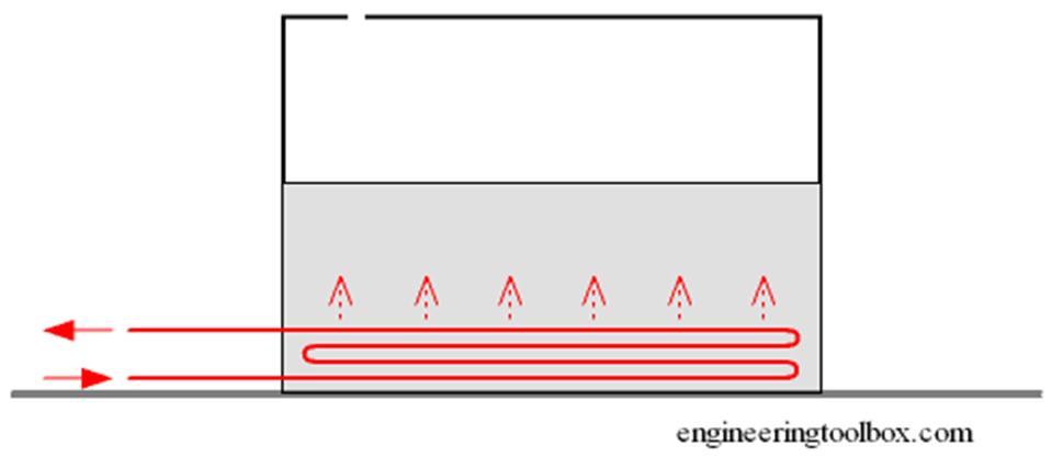
- Submerged steam coils – A widely used form of heat transfer involves the installation inside a tank of a steam coil immersed in a process fluid.
- Steam jackets-Steam circulates in the annular space space between a jacket and the vessel walls, and heat is transferred through the wall of the vessel.
SUBMERGED STEAM COILS
The use of tank coils is particularly common in marine applications where cargoes of crude oil, edible oils, tallow and molasses are heated in deep tanks. Many of these liquids are difficult to handle at ambient temperatures due to their viscosity. Steam heated coils are used to raise the temperature of these liquids, lowering their viscosity so that they become easier to pump.
Tank coils are also extensively used in electroplating and metal treatment. Electroplating involves passing articles through several process tanks so that metallic coatings can be deposited on to their surfaces. One of the first stages in this process is known as pickling, where materials such as steel and copper are treated by dipping them in tanks of acid or caustic solution to remove any scale or oxide (e.g. rust) which may have formed.
Steam coil sizing
Having determined the energy required, and with knowledge of the steam pressure/temperature in the coil, the heat transfer surface may be determined using Equation 2.5.3:
The heat transfer area calculated is equivalent to the surface area of the coil, and will enable an appropriate size and layout to be specified.
Determining the ‘U’ value
To calculate the heat transfer area, a value for the overall heat transfer coefficient, U, must be chosen. This will vary considerably with the thermal and transport properties of both fluids and a range of other conditions.
On the product side of the coil a thermal boundary layer will exist in which there is a temperature gradient between the surface and the bulk fluid. If this temperature difference is relatively large, then the natural convective currents will be significant, and the heat transfer coefficient will be high.
Assisted circulation (such as stirring) that will induce forced convection, will also result in higher coefficients. As convection is partially dependent on the bulk motion of the fluid, the viscosity (which varies with temperature) also has an important bearing on the thermal boundary layer.
Additional variations can also occur on the steam side of the coil, especially with long lengths of pipe. The coil inlet may have a high steam velocity and may be relatively free from water.
However, further along the length of the coil the steam velocity may be lower, and the coil may be running partially full of water. In very long coils, such as those sometimes found in seagoing tankers or in large bulk storage tanks, a significant pressure drop occurs along the length of the coil. To achieve the mean coil temperature, an average steam pressure of approximately 75% of the inlet pressure may be used. In extreme cases the average pressure used may be as low as 40% of the inlet pressure. Another variable is the coil material itself. The thermal conductivity of the coil material may vary considerably.
However, overall heat transfer is governed to a large extent by the heat-resistant films, and the thermal conductivity of the coil material is not as significant as their combined effect. Table 2.10.1 provides typical overall heat transfer coefficients for various conditions of submerged steam coil application. ‘U’ values for steam pressures between 2 bar g and 6 bar g should be found by interpolation of the data in the table.
Table 2.10.1 Heat emission rates for steam coils submerged in water
| Customary overall heat transfer coefficients | U (W/m² °C) | |
| Mean steam/water temperature difference around 30 °C | 550 – 1 300 | |
| Mean steam/water temperature difference around 60 °C | 1 000 – 1 700 | |
| Mean steam/water temperature difference around 110 °C | 1 300 – 2 700 | |
| Recommended rates | U (W/m² °C) | |
| Lower pressure coils | (<2 bar g) with natural circulation of water | 550 |
| Higher pressure coils | (>6 bar g) with natural circulation of water | 1 100 |
| Lower pressure coils | (<2 bar g) with assisted circulation of water | 1 100 |
| Higher pressure coils | (>6 bar g) with assisted circulation of water | 1 700 |
The range of figures shown in Table 2.10.1 demonstrates the difficulty in providing definitive ‘U’ values. Customary figures at the higher end of the scale will apply to installations that are supplied with clean dry steam, small coils and good condensate drainage. The lower end is more applicable to poor quality steam, long coils and poor condensate drainage.
The recommended overall heat transfer coefficients will apply to typical conditions and installations.
These recommended rates are empirically derived, and will generally ensure that a generous safety margin applies to the coil sizing.
In the case of fluids other than water, the heat transfer coefficient will vary even more widely due to the way in which viscosity varies with temperature. However, the values shown in Table 2.10.2 will serve as a guide for some commonly encountered substances, while Table 2.10.3 gives typical surface areas of pipes per metre length.
Table 2.10.2 Heat emission rates for steam coils submerged in miscellaneous liquids
| Medium pressure steam | (2 – 6 bar g) with natural liquid convection | U (W/m² °C) |
| Light oils | 170 | |
| Heavy oils | 80 – 110 | |
| Fats * | 30 – 60 | |
| Medium pressure steam | (2 – 6 bar g) with forced liquid convection | U (W/m² °C) |
| Light oils | (200 sec Redwood at 38 °C) | 550 |
| Medium oils | (1 000 sec Redwood at 38 °C) | 340 |
| Heavy oils | (3 500 sec Redwood at 38 °C) | 170 |
| Molasses ** | (10 000 sec Redwood at 38 °C) | 85 |
| Fats * | (50 000 sec Redwood at 38 °C) | 55 |
* Certain materials such as tallow and margarine are solid at normal temperatures but have quite low viscosities in the molten state.
** Commercial molasses frequently contains water and the viscosity is much lower.
Table 2.10.3 Nominal surface areas of steel pipes per meter length
| Nominal bore (mm) | 15 | 20 | 25 | 32 | 40 | 50 | 65 | 80 | 100 |
| Surface area (m²/m) | 0.067 | 0.085 | 0.106 | 0.134 | 0.152 | 0.189 | 0.239 | 0.279 | 0.358 |
Example 2.10.1
Example 2.9.1
For the tank shown in Figure 2.9.3, determine:
Part 1. The mean heat transfer rate required during start-up.
Part 2. The maximum heat transfer rate required during operation.
Fig 2.9.3 Overall heat transfer coefficients for oil tanks
The tank is unlagged and open topped and is situated on a concrete floor inside a factory.
It is 3 m long by 3 m wide by 2 m high.
Tank total surface area = 24 m² (excluding base).
Heat transfer coefficient from tank/air, U1 = 11 W/m² °C.
The tank is 2/3 full of a weak acid solution (cp = 3.9 kJ/kg °C) which has the same density as water (1 000 kg/m³)
The tank is fabricated from 15 mm mild steel plate. (Density = 7 850 kg/m³, cp = 0.5 kJ/kg °C)
The tank is used on alternate days, when the solution needs to be raised from the lowest considered ambient temperature of 8 °C to 60 °C in 2 hours, and remain at that temperature during the day.
When the tank is up to temperature, a 500 kg steel article is to be dipped every 20 minutes without the tank overflowing. (cp = 0.5 kJ/kg °C
Continuing from Example 2.9.1 determine:
- Part 1. The average steam mass flowrate during start-up. (Mean heat load = 367 kW)
- Part 2. The heat transfer area required
- Part 3. A recommended coil surface area.
- Part 4. The maximum steam mass flowrate with the recommended heat transfer area.
- Part 5. A recommendation for installation, including coil diameter and layout.
The following additional information has been provided:
- Steam pressure onto the control valve = 2.6 bar g (3.6 bar a).
- A stainless steel steam coil provides heat.
- Heat transfer coefficient from steam/coil/liquid, U = 650 W/m² °C
Part 1 Calculate the average steam mass flowrate during start-up
Steam pressure onto the control valve = 2.6 bar g (3.6 bar a)
Critical pressure drop (CPD) will occur across the control valve during start-up, therefore the minimum steam pressure in the heating coil should be taken as 58% of upstream absolute pressure. An explanation of this is given in Block 5.
Part 2 Calculate the heat transfer area required
Part 3 A recommendation for coil surface area
Because of the difficulties in providing accurate ‘U’ values, and to allow for future fouling of the heat exchange surface, it is usual to add 10% to the calculated heat transfer area.
Part 4 the maximum steam mass flowrate with the recommended heat transfer area
Maximum heat transfer (and hence steam demand) will occur when the temperature difference between the steam and the process fluid is at its maximum, and should take into consideration the extra pipe area allowed for fouling.
(a) Consider the maximum heating capacity of the coil Q̇(coil)
(b) Steam flowrate to deliver 519 kW
Part 5 A recommendation for installation, including coil diameter and layout
a) Determine coil diameter and length
It may be difficult to accommodate this length of large bore heating pipe to install in a 3 m × 3 m tank.
One solution would be to run a bank of parallel pipes between steam and condensate manifolds, set at different heights to encourage condensate to run to the lower (condensate) manifold. The drain line must fall from the bottom of the condensate manifold down to the steam trap (or pump-trap).
See Figure 2.10.1 for a suggested layout.
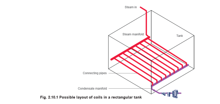
Note the steam supply is situated at one end of its manifold, whilst the trap set is at the other end. This will help steam to flow and push condensate through the coils.
In the application, the steam and condensate headers would each be 2.8 m long. As the condensate manifold is holding condensate, the heat from it will be small compared to the steam manifold and this can be ignored in the calculation.
The steam manifold should be 100 mm diameter as determined by the previous velocity calculation. This will provide a heating area of:
2.8 m x 0.358 m²/m = 1.0 m²
Consequently 7 m² – 1 m² = 6 m² of heat transfer area is still required and must be provided by the connecting pipes.
Arbitrarily selecting 32 mm pipe as a good compromise between robustness and workability:
It is necessary to confirm the steam velocity through the connecting tubes:
On the basis of proportionality of heat transfer area, the steam header will condense
Other Types of steam coil layouts
The design and layout of the steam coil will depend on the process fluid being heated. When the process fluid to be heated is a corrosive solution, it is normally recommended that the coil inlet and outlet connections are taken over the lip of the tank, as it is not normally advisable to drill through the corrosion resistant linings of the tank side. This will ensure that there are no weak points in the tank lining, where there is a risk of leakage of corrosive liquids. In these cases the coil itself may also be made of corrosion resistant material such as lead covered steel or copper, or alloys such as titanium.
However, where there is no danger of corrosion, lifts over the tank structure should be avoided, and the steam inlet and outlet connections may be taken through the tank side. The presence of any lift will result in waterlogging of a proportion of the coil length, and possibly water hammer, noise and leaking pipework.
Steam heating coils should generally have a gradual fall from the inlet to the outlet to ensure that condensate runs toward the outlet and does not collect in the bottom of the coil.
Where a lift is unavoidable, it should be designed to include a seal arrangement at the bottom of the lift and a small-bore dip pipe, as shown in Figure 2.10.2.
The seal arrangement allows a small amount of condensate to collect to act as a water seal, and prevents the occurrence of steam locking. Without this seal, steam can pass over any condensate collecting in the bottom of the pipe, and close the steam trap at the top of the riser.
The condensate level would then rise and form a temporary water seal, locking the steam between the bottom of the riser and the steam trap. The steam trap remains closed until the locked steam condenses, during which time the coil continues to waterlog.
When the locked steam condenses and the steam trap opens, a slug of water is discharged up the riser. As soon as the water seal is broken, steam will enter the rising pipe and close the trap, while the broken column of water falls back to lie at the bottom of the heating coil.
The small bore dip pipe will only allow a very small volume of steam to become locked in the riser. It enables the water column to be easily maintained without steam bubbling through it, ensuring there is a steady and continuous condensate flow to the outlet.
When the seal is ultimately broken, a smaller volume of water will return to the heating coil than with an unrestricted large bore riser, but as the water seal arrangement requires a smaller volume of condensate to form a water seal, it will immediately re-form.
If the process involves articles being dipped into the liquid, it may not be convenient to install the coil at the bottom of the tank – it may be damaged by the objects being immersed in the solution.
Also, during certain processes, heavy deposits will settle at the bottom of the tank and can quickly cover the heating surface, inhibiting heat transfer.
For these reasons side hung coils are often used in the electroplating industry. In such cases serpentine or plate-type coils are arranged down the side of a tank, as shown in Figure 2.10.3. These coils should also have a fall to the bottom with a water seal and a small bore dip-pipe.This arrangement has the advantage that it is often easier to install, and also easier to remove for periodic cleaning if required.
If articles are to be dipped into the tank, it may not be possible to use any sort of agitator to induce forced convection and prevent temperature gradients occurring throughout the tank. Whether bottom or side coils are used, it is essential that they are arranged with adequate coverage so that the heat is distributed evenly throughout the bulk of the liquid.
The diameter of the coil should provide sufficient length of coil for good distribution. A short length of coil with a large diameter may not provide adequate temperature distribution. However a very long continuous length of coil may experience a temperature gradient due to the pressure drop from end to end, resulting in uneven heating of the liquid.
- Control valve arrangement
The control valve set may be either one or two valves in parallel. A single control valve, large enough to cope with the maximum flowrate encountered at start-up, may be unable to control flow accurately at the minimum expected flowrate. This could cause erratic temperature control.
An alternative is to fit two temperature control valves in parallel:
- One valve (running valve) sized to control at the lower flowrate.
- A second valve (starting valve) to pass the difference between the capacity of the first valve, and the maximum flowrate.
The starting valve would have a set-point slightly lower than the running valve, so it would close first, leaving the running valve to control at low loads.
- Sizing the control valve
The control valve set (either one valve or two valves in parallel).
The coil has been sized on mean heat transfer values. However, it may be better to size the control valve to supply the maximum (start-up) load. With large coils in tanks, this will help to maintain a degree of steam pressure throughout the length of the coil when the steam is turned on, helping to push condensate through the coil to the steam trapping device. If the control valve were sized on mean values, steam pressure in the coil at start-up will tend to be lower and the coil may flood
Using one valve
Continuing with Example 2.10.1 the maximum steam load is 850 kg/h and the coil is designed to deliver this at a pressure of 1.1 bar g. A steam valve sizing chart would show that a Kv of about 20 is required to pass 850 kg/h of steam with a pressure of 2.6 bar g at the inlet of the control valve, and Critical Pressure Drop (CPD) across the valve. (Module 6.4 will show how the valve size can be determined by calculation).
A DN40 control valve with a larger Kvs of 25 would therefore need to be selected for the application.
If one valve is to be used, this valve must ensure the maximum heat load is catered for, while maintaining the required steam pressure in the coil to assist the drainage of condensate from it at start-up. However, for reasons previously explained, two valves may be better.
The running load is 52 kW and with the coil running at 1.1 bar g, the running steam load:
The steam valve sizing chart shows a Kv of 2 is required to pass 85 kg/h with 3.6 bar upstream, operating at critical pressure drop.
A DN15 KE type valve (Kvs = 4) and a DN25 piston actuated valve (Kvs = 18.6) operating together will cater for the start-up load. When approaching the control temperature, the larger valve would be set to shut down, allowing the smaller valve to give good control.
The condensate removal device
The selection and sizing of the condensate removal device will be very much influenced by the condensate backpressure. For the purpose of this example, it is assumed the backpressure is atmospheric pressure. The device should be sized so it is able to satisfy both of the following
conditions:
- Pass 850 kg/h of condensate with 1.1 bar g in the coil, i.e. the full-load condition.
- Pass the condensate load when steam pressure in the coil equals the condensate backpressure, i.e. the stall load condition.
If the steam trap is only sized on the first condition, it is possible that it may not pass the stall load (the condition where the product approaches its required temperature and the control valve modulates to reduce steam pressure). The stall load may be considerable. With respect to non-flow type applications such as tanks, this may not be too serious from a thermal viewpoint because the contents of the tank will almost be at the required temperature, and have a huge reservoir of heat.
Any reduction in heat transfer at this part of the heating process may therefore have little immediate effect on the tank contents.
However, condensate will back up into the coil and waterhammer will occur, along with its associated symptoms and mechanical stresses. Tank coils in large circular tanks tend to be of robust construction, and are often able to withstand such stresses. Problems can however occur in rectangular tanks (which tend to be smaller), where vibration in the coil will have more of an effect on the tank structure. Here, the energy dissipated by the waterhammer causes vibration, which can be detrimental to the life of the coil, the tank, and the steam trap, as well as creating unpleasant noise.
With respect to flow-type applications such as plate heat exchangers, a failure to consider the stall condition will usually have serious implications. This is mainly due to the small volume in the heat exchanger. For heat exchangers, any unwanted reduction in the heating surface area, such as that caused by condensate backing up into the steam space, can affect the flow of heat through the heating surface. This can cause the control system to become erratic and unstable, and processes requiring stable or accurate control can suffer with poor performance.
If heat exchangers are oversized, sufficient heating surface may remain when condensate backs up into the steam space, and reduction of thermal performance may not always occur.
However, with heat exchangers not designed to cope with the effects of waterlogging, this can lead to corrosion of the heating surface, inevitably reducing the service life of the exchanger. Waterlogging can, in some applications, be costly. Consider a waterlogging air heater frost coil. Cold air at 4 °C flowing at 3 m/s can soon freeze condensate locked in the coils, resulting in premature and unwarranted failure. Proper drainage of condensate is essential to maintain the service life of any heat exchanger and air heater.
Steam traps are devices which modulate to allow varying amounts of condensate to drain from applications under varying conditions. Float traps are steam traps designed to modulate and release condensate close to steam temperature, offering maximum plant performance, maximum plant life, and maximum return on plant investment. When stall conditions occur, and a steam trap cannot be used, an automatic pump-trap or pump and trap in combination will ensure correct condensate drainage at all times, thus maximising the thermal capability and lifetime costs of the plant.
STEAM JACKETS
The most commonly used type of steam jacket consists simply of an outer cylinder surrounding the vessel, as shown in Figure 2.10.4. Steam circulates in the outer jacket and condenses on the wall of the vessel. Jacketed vessels may also be lagged or may contain an internal air space surrounding the jacket. This is to ensure that as little steam as possible condenses on the outer jacket wall, and that the heat is transferred inwards to the vessel. The heat transfer area (the vessel wall surface area), can be calculated in the same manner as with a steam coil, using Equation 2.5.3 and the overall heat Transfer coefficients provided in Table 2.10.4.
Although steam jackets may generally be less thermally efficient than submerged coils, due to radiation losses to the surroundings, they do allow space for the vessels to be agitated so that heat transfer is promoted. The U values listed in Table 2.10.4. are for moderate nonproximity agitation.
Commonly the vessel walls are made from stainless steel or glass lined carbon steel. The glass lining will offer an additional corrosion resistant layer. The size of the steam jacket space will depend on the size of the vessel, but typically the width may be between 50 mm and 300 mm.
Table 2.10.4 Overall heat transfer coefficients for steam jackets
| Process fluid or product | Wall material | U (W/m² °C) |
| Water | Stainless steel | 850 – 1 700 |
| Glass-lined carbon steel | 400 – 570 | |
| Aqueous solution | Stainless steel | 450 – 1 140 |
| Glass-lined carbon steel | 285 – 480 | |
| Organics | Stainless steel | 285 – 850 |
| Glass-lined carbon steel | 170 – 400 | |
| Light oil | Stainless steel | 340 – 910 |
| Glass-lined carbon steel | 230 – 425 | |
| Heavy oil | Stainless steel | 57 – 285 |
| Glass-lined carbon steel | 57 – 230 |
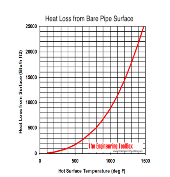
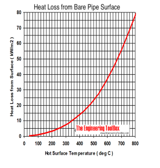
Pipes – Bare Surface Heat Loss
Heat loss vs. surface temperature.
The diagrams below indicates heat loss from uninsulated pipes with bare surfaces at still-air conditions and air temperature 70 oF (21 oC). The emissivity coefficient of the surface is 0.95.
 |  |
The overall heat transfer coefficients for steam coils with medium pressure – or hot water coils or pipes – submerged in oil or fat:
| Submerged Coils – Heat Transfer Coefficients | ||
| Type of Coil | Heat Transfer Coefficient – U – | |
| (W/m2 oC) | (Btu/hr ft2 oF) | |
| Steam to Aqueous Solutions, agitated | 800 – 1200 | 140 – 210 |
| Steam to Aqueous Solutions, natural convection | 340 – 570 | 60 – 100 |
| Steam to Light Oil, natural convection | 170 | 30 |
| Submerged Coils – Heat Transfer Coefficients | ||
| Type of Coil | Heat Transfer Coefficient – U – | |
| (W/m2 oC) | (Btu/hr ft2 oF) | |
| Steam to Heavy Oil, natural convection | 85 – 115 | 15 – 20 |
| Steam to Heavy Oil, agitated | 140 – 310 | 25 – 55 |
| Steam to Fat, natural convection | 30 – 60 | 5 – 10 |
| Steam to Organics, agitated | 510 – 800 | 90 – 140 |
| Hot Water to Oil, natural convection | 34 – 140 | 6 – 25 |
| Hot Water to Water, natural convection | 200 – 370 | 35 – 65 |
| Hot Water to Water, agitated | 480 – 850 | 90 – 150 |
| Heat transfer oil to Organics, agitated | 140 – 280 | 25 – 50 |
| Salt brine to Water, agitated | 280 – 630 | 50 – 110 |
| Cooling Water to Glycerine, agitated | 280 – 430 | 50 – 75 |
Example – Heat Transfer from a Steam Coil
A 50 mm steam coil with outside diameter 60.3 mm(0.0603 m) and length 10 m with 1 bar absolute pressure and steam temperature 120 oC is submerged in an oil bath with temperature 50 oC.
The surface area of the coil can be calculated by multiplying the pipe circumference with pipe length as A = π (0.0603 m) (10 m) = 1.89 m2
From the table above the heat transfer coefficient is 170 W/m2 oC for “Steam to Light Oil, Natural Convection”. The heat transfer can be calculated as
Q = (1.89 m2)((120 oC) – (50 oC))(170 W/m2 oC) = 22491 W
7. Steam traps:
Steam trap selection guide – Float & Thermostatic, Inverted Bucket, Bimetal Thermostatic, Impulse and Thermodynamic Disc steam traps.
A steam trap is a self-contained valve which automatically drains the condensate from a steam containing enclosure while remaining tight to live steam, or if necessary, allowing steam to flow at controlled or adjusted rate. Most steam traps pass non-condensable gases like air while remaining tight to live steam.
A steam trap should
- discharge condensate immediately and completely
- not leak steam
- discharge non-condensable gases like air
There are three primary categories of steam traps:
- mechanical
- thermostatic
- thermodynamic
Popular traps in these categories includes the float steam trap, the thermostatic steam trap, the inverted bucket steam trap and the thermodynamic disc steam trap. Which one is preferred depends on the application.
A steam trap prime missions is to remove condensate and air preventing escape of live steam from the distribution system. The steam trap must adapt to the application. A disc thermodynamic steam trap should never be used together with a modulating heat exchanger – and a floating ball steam trap may be overkill for draining steam pipes.
The table below can be used as a short guide for the selection of steam traps:
| Steam Trap Selection Guide | |||||
| Type of Steam Trap | Operation | Normal Failure Mode | |||
| No or little load | Light Load | Normal Load | Heavy Load | ||
| Float & Thermostatic | No action | Usually continuous. May cycle. | Usually continuous. May cycle. | Continuous | Closed |
| Inverted Bucket | Small dribble, may leak steam with very little condensate load | May dribble | Intermittent | Continuous | Variable |
| Bi-metal Thermostatic | No action | Usually dribble action | May blast at high pressures | Continuous | Open |
| Impulse | Small dribble | Usually continuous with blast at high loads | Usually continuous with blast at high loads | Continuous | Open |
| Thermodynamic Disc | No action | Intermittent | Intermittent | Continuous | Open |
Thermostatic Steam Traps
There are two basic designs for the thermostatic steam trap, a bimetallic and a balanced pressure design. Both designs use the difference in temperature between live steam and condensate or air to control the release of condensate and air from the steam line.
In a thermostatic bimetallic trap it is common that an oil filled element expands when heated to close a valve against a seat. It may be possible to adjust the discharge temperature of the trap – often between 60 oC and 100 oC.
This makes the thermostatic trap suited to get rid of large quantities of air and cold condensate at the start-up condition. On the other hand the thermostatic trap will have problems to adapt to the variations common in modulating heat exchangers.
- intermittent operation
- fair energy conservation
- fair resistance to wear
- good corrosion resistance
- poor resistance to hydraulic shocks (good for bi-metal traps)
- do not vent air and CO2 at steam temperature
- good ability to vent air at very low pressure
- excellent ability to handle start up air loads
- excellent operation against back pressure
- good resistance to damage from freezing
- good ability to purge system
- excellent performance on very light loads
- delayed responsiveness to slugs of condensate
- fair ability to handle dirt
- small comparative physical size
- poor ability to handle flash steam
- open or closed at mechanical failure depending of the construction
Float Steam Traps
In the float steam trap a valve is connected to a float in such a way that a valve opens when the float rises.
The float steam trap adapts very well to varying conditions as is the best choice for modulating heat exchangers, but the float steam trap is relatively expensive and not very robust against water hammers.
- continuous operation but may cycle at high pressures
- no action at no load, continuous at full load
- good energy conservation
- good resistance to wear
- good corrosion resistance
- poor resistance to hydraulic shocks
- do not vent air and CO2 at steam temperature
- excellent ability to vent air at very low pressure
- excellent ability to handle start up air loads
- excellent operation against back pressure
- poor resistance to damage from freezing
- fair ability to purge system
- excellent performance on very light loads
- immediate responsiveness to slugs of condensate
- poor ability to handle dirt
- large comparative physical size
- poor ability to handle flash steam
- closed at mechanical failure
Inverted Bucket Steam Trap
In an inverted bucket steam trap a leverage system multiplies the force provided by the bucket to open a valve against the pressure. The bucket is open at the bottom and robust against water hammers.
- intermittent operation – condensate drainage is continuous, discharge is intermittent
- small dribble at no load – may leak steam, intermittent at light and normal load, continuous at full load
- good energy conservation
- good resistance to wear
- good corrosion resistance
- excellent resistance to hydraulic shocks
- vents air and CO2 at steam temperature
- poor ability to vent air at very low pressure
- fair ability to handle start up air loads
- excellent operation against back pressure
- good resistance to damage from freezing
- good ability to purge system
- good performance on very light loads – but may leak steam if there almost no condensate load for the bucket to float
- immediate responsiveness to slugs of condensate
- excellent ability to handle dirt
- large comparative physical size
- fair ability to handle flash steam
- open at mechanical failure
Thermodynamic Disc Steam Traps
The thermodynamic trap is an robust steam trap with simple operation. The trap operates by means of the dynamic effect of flash steam as it passes through the trap.
- intermittent operation
- poor energy conservation
- poor resistance to wear
- excellent corrosion resistance
- excellent resistance to hydraulic shocks
- do not vent air and CO2 at steam temperature
- not recommended at low pressure operations
- poor ability to handle start up air loads
- poor operation against back pressure
- good resistance to damage from freezing
- excellent ability to purge system
- poor performance on very light loads
- delayed responsiveness to slugs of condensate
- poor ability to handle dirt
- small comparative physical size
- poor ability to handle flash steam
- open at mechanical failure
8. Condensate and its recovery
Condensate Pipe Lines – Sizing
Flow and pressure loss in condensate return lines – SI Units.
When sizing condensate return lines in steam distribution system – remember that the maximum condensate flow is achieved during plant start up when pipes and equipment are heated up.
A rule of thumb – the condensate load used to design condensate pipe lines should be twice the maximum production load.
| Steam Condensate Pipe Lines – Sizing | |||||||||
| Pressure loss | Condensate Flow (kg/hour) | ||||||||
| Pipe Size (mm, inch) | |||||||||
| 15 | 20 | 25 | 32 | 40 | 50 | 65 | 80 | ||
| (Pa/m) | (mbar/m) | 1/2 | 3/4 | 1 | 1 1/4 | 1 1/2 | 2 | 2 1/2 | 3 |
| 28 | 0.28 | 90 | 209 | 380 | 865 | 1320 | 2554 | 5194 | 8079 |
| 29 | 0.29 | 92 | 214 | 400 | 878 | 1340 | 2590 | 5271 | 8196 |
| 30 | 0.3 | 93 | 218 | 403 | 890 | 1361 | 2631 | 5348 | 8314 |
| 33 | 0.33 | 97 | 226 | 414 | 930 | 1420 | 2744 | 5579 | 8677 |
| 39 | 0.39 | 107 | 249 | 469 | 1028 | 1565 | 3025 | 6142 | 9526 |
| 40 | 0.4 | 108 | 253 | 476 | 1040 | 1583 | 3062 | 6214 | 9639 |
| 43 | 0.43 | 113 | 263 | 496 | 1079 | 1646 | 3180 | 6454 | 10024 |
| 45 | 0.45 | 116 | 270 | 508 | 1107 | 1687 | 3261 | 6618 | 10297 |
| 47 | 0.47 | 119 | 277 | 521 | 1134 | 1728 | 3338 | 6777 | 10523 |
| 50 | 0.5 | 123 | 286 | 538 | 1172 | 1787 | 3447 | 6949 | 10859 |
| 53 | 0.53 | 127 | 296 | 557 | 1211 | 1846 | 3565 | 7235 | 11249 |
| 55 | 0.55 | 130 | 302 | 569 | 1238 | 1887 | 3638 | 7380 | 11476 |
| 57 | 0.57 | 133 | 308 | 580 | 1261 | 1923 | 3710 | 7525 | 11703 |
| 59 | 0.59 | 135 | 314 | 591 | 1288 | 1959 | 3783 | 7666 | 11884 |
| 61 | 0.61 | 138 | 320 | 602 | 1311 | 1996 | 3851 | 7806 | 12111 |
| 64 | 0.64 | 141 | 327 | 615 | 1338 | 2041 | 3933 | 7970 | 12383 |
| 67 | 0.67 | 146 | 337 | 634 | 1379 | 2100 | 4051 | 8210 | 12746 |
| 69 | 0.69 | 148 | 343 | 645 | 1402 | 2136 | 4119 | 8342 | 12973 |
| 71 | 0.71 | 150 | 348 | 655 | 1424 | 2168 | 4182 | 8473 | 13154 |
| 73 | 0.73 | 152 | 354 | 665 | 1447 | 2200 | 4246 | 8600 | 13336 |
| 76 | 0.76 | 155 | 359 | 675 | 1465 | 2236 | 4305 | 8723 | 13563 |
| 77 | 0.77 | 157 | 365 | 685 | 1488 | 2268 | 4368 | 8850 | 13744 |
| 78 | 0.78 | 158 | 366 | 689 | 1497 | 2282 | 4390 | 8900 | 13812 |
| Steam Condensate Pipe Lines – Sizing | |||||||||
| Pressure loss | Condensate Flow (kg/hour) | ||||||||
| Pipe Size (mm, inch) | |||||||||
| 15 | 20 | 25 | 32 | 40 | 50 | 65 | 80 | ||
| (Pa/m) | (mbar/m) | 1/2 | 3/4 | 1 | 1 1/4 | 1 1/2 | 2 | 2 1/2 | 3 |
| 80 | 0.8 | 160 | 370 | 695 | 1510 | 2300 | 4427 | 8972 | 13925 |
| 82 | 0.82 | 162 | 375 | 704 | 1529 | 2331 | 4491 | 9072 | 14407 |
| 88 | 0.88 | 168 | 391 | 733 | 1590 | 2427 | 4536 | 9453 | 14651 |
| 90 | 0.9 | 170 | 395 | 740 | 1606 | 2449 | 4717 | 9548 | 14787 |
| 98 | 0.98 | 179 | 414 | 777 | 1696 | 2567 | 4944 | 10025 | 15513 |
| 100 | 1 | 180 | 418 | 785 | 1701 | 2590 | 4990 | 10115 | 15649 |
| 114 | 1.14 | 194 | 450 | 845 | 1832 | 2790 | 5366 | 10841 | 16828 |
| 118 | 1.18 | 198 | 457 | 857 | 1860 | 2830 | 5443 | 11022 | 17055 |
| 120 | 1.2 | 199 | 462 | 867 | 1880 | 2860 | 5502 | 11113 | 17282 |
| 131 | 1.31 | 209 | 484 | 907 | 1969 | 2994 | 5761 | 11657 | 18053 |
| 137 | 1.37 | 215 | 497 | 931 | 2018 | 3071 | 5906 | 11948 | 18507 |
| 140 | 1.4 | 216 | 502 | 939 | 2037 | 3103 | 5965 | 12066 | 18688 |
| 147 | 1.47 | 224 | 516 | 966 | 2096 | 3189 | 6128 | 12383 | 19187 |
| 157 | 1.57 | 231 | 534 | 1002 | 2168 | 3298 | 6337 | 12814 | 19822 |
| 160 | 1.6 | 234 | 541 | 1011 | 2195 | 3340 | 6409 | 12973 | 20049 |
| 163 | 1.63 | 237 | 546 | 1025 | 2218 | 3370 | 6477 | 13109 | 20276 |
| 176 | 1.76 | 246 | 570 | 1066 | 2309 | 3511 | 6740 | 13608 | 21092 |
| 180 | 1.8 | 249 | 576 | 1075 | 2331 | 3547 | 6808 | 13744 | 21319 |
| 196 | 1.96 | 261 | 603 | 1129 | 2440 | 3710 | 7130 | 14379 | 22317 |
| 200 | 2 | 265 | 611 | 1143 | 2472 | 3760 | 7221 | 14560 | 22589 |
| 212 | 2.12 | 273 | 629 | 1179 | 2549 | 3874 | 7430 | 15014 | 23270 |
| 216 | 2.16 | 275 | 634 | 1188 | 2567 | 3905 | 7493 | 15132 | 23451 |
| 220 | 2.2 | 278 | 641 | 1200 | 2595 | 3942 | 7570 | 15277 | 23678 |
| 229 | 2.29 | 284 | 655 | 1225 | 2649 | 4028 | 7729 | 15604 | 24177 |
| 235 | 2.35 | 288 | 664 | 1243 | 2689 | 4086 | 7843 | 15840 | 24522 |
| 240 | 2.4 | 292 | 672 | 1256 | 2719 | 4129 | 7927 | 16017 | 24780 |
| 245 | 2.45 | 295 | 679 | 1270 | 2749 | 4173 | 8010 | 16193 | 25039 |
| 255 | 2.55 | 301 | 694 | 1297 | 2806 | 4260 | 8176 | 16520 | 25556 |
| 260 | 2.6 | 304 | 701 | 1311 | 2834 | 4304 | 8260 | 16683 | 25814 |
| Steam Condensate Pipe Lines – Sizing | |||||||||
| Pressure loss | Condensate Flow (kg/hour) | ||||||||
| Pipe Size (mm, inch) | |||||||||
| 15 | 20 | 25 | 32 | 40 | 50 | 65 | 80 | ||
| (Pa/m) | (mbar/m) | 1/2 | 3/4 | 1 | 1 1/4 | 1 1/2 | 2 | 2 1/2 | 3 |
| 261 | 2.61 | 305 | 703 | 1315 | 2844 | 4318 | 8287 | 16738 | 25900 |
| 274 | 2.74 | 313 | 721 | 1348 | 2917 | 4331 | 8501 | 17173 | 26554 |
| 277 | 2.77 | 315 | 727 | 1356 | 2935 | 4459 | 8555 | 17282 | 26717 |
| 280 | 2.8 | 317 | 730 | 1363 | 2948 | 4479 | 8593 | 17357 | 26839 |
| 294 | 2.94 | 325 | 749 | 1402 | 3025 | 4595 | 8813 | 17781 | 27533 |
| 300 | 3 | 328 | 757 | 1414 | 3055 | 4641 | 8900 | 17956 | 27803 |
| 310 | 3.1 | 335 | 771 | 1438 | 3112 | 4726 | 9063 | 18280 | 28305 |
| 314 | 3.14 | 336 | 775 | 1446 | 3129 | 4752 | 9074 | 18380 | 28459 |
| 320 | 3.2 | 340 | 784 | 1462 | 3163 | 4825 | 9204 | 18579 | 28767 |
| 327 | 3.27 | 344 | 792 | 1479 | 3198 | 4853 | 9299 | 18779 | 29076 |
| 333 | 3.33 | 348 | 801 | 1495 | 3230 | 4904 | 9408 | 18979 | 29366 |
| 340 | 3.4 | 351 | 809 | 1511 | 3263 | 4955 | 9516 | 19178 | 29656 |
| 342 | 3.42 | 353 | 813 | 1520 | 3279 | 4980 | 9571 | 19278 | 29801 |
| 353 | 3.53 | 358 | 825 | 1541 | 3328 | 5054 | 9707 | 19550 | 30237 |
| 359 | 3.59 | 362 | 834 | 1556 | 3361 | 5103 | 9798 | 19732 | 30527 |
| 360 | 3.6 | 363 | 835 | 1558 | 3365 | 5109 | 9809 | 19754 | 30564 |
| 372 | 3.72 | 369 | 850 | 1585 | 3423 | 5201 | 9979 | 20094 | 31108 |
| 376 | 3.76 | 371 | 854 | 1592 | 3438 | 5225 | 10024 | 20185 | 31253 |
| 380 | 3.8 | 373 | 859 | 1601 | 3457 | 5254 | 10081 | 20299 | 31423 |
| 392 | 3.92 | 379 | 873 | 1628 | 3515 | 5339 | 10251 | 20639 | 31933 |
| 400 | 4 | 383 | 883 | 1646 | 3554 | 5398 | 10342 | 20866 | 32274 |
| 408 | 4.08 | 388 | 892 | 1665 | 3592 | 5457 | 10433 | 21092 | 32614 |
| 412 | 4.12 | 390 | 896 | 1672 | 3608 | 5479 | 10478 | 21174 | 32750 |
| 420 | 4.2 | 394 | 906 | 1690 | 3646 | 5536 | 10592 | 21378 | 33090 |
| 425 | 4.25 | 396 | 912 | 1701 | 3670 | 5570 | 10660 | 21500 | 33294 |
Equipment Piping and Condensate Load
Typical maximum condensate load and equipment outlet pipe size:
| Steam Condensate Pipe Lines – Equipment Outlet Pipe Sizes | |
| Maximum Condensate Load (kg/h) | Outlet Pipe Size (mm, (in)) |
| 200 | 15 (1/2) |
| 500 | 20 (3/4) |
| 1000 | 25 (1) |
| 2000 | 32 (1 1/4) |
| 3000 | 40 (1 1/2) |
| 5000 | 50 (2) |
| > 5000 | 65 – 100 (2 1/2 – 4) |
9. Flash steam and its recovery:
| Flash Steam Generation from Condensate vs. Steam Pressure – SI-units | |||||||
| Absolute Pressure before the condensate trap (kN/m2) | Temperature (oC) | Percent Flash Steam of Condensate (%) | |||||
| Absolute Pressure after the condensate trap (kN/m2) | |||||||
| 400 | 260 | 170 | 101.33 | 65 | 35 | ||
| 1500 | 198.3 | 11.3 | 14.0 | 16.4 | 18.9 | 20.4 | 23.2 |
| 1150 | 186.0 | 8.7 | 11.5 | 13.9 | 16.5 | 18.4 | 20.9 |
| 800 | 170.4 | 5.5 | 8.2 | 10.8 | 13.4 | 15.4 | 17.9 |
| 650 | 162.4 | 3.7 | 6.5 | 9.1 | 11.8 | 13.7 | 16.3 |
| 500 | 151.8 | 1.6 | 4.6 | 7.1 | 9.8 | 11.8 | 14.4 |
| 400 | 143.6 | 3.0 | 5.5 | 8.3 | 10.3 | 12.9 | |
| 260 | 128.7 | 2.6 | 5.4 | 7.5 | 10.2 | ||
| 170 | 115.2 | 2.8 | 5.0 | 7.7 | |||
| 101.33 | 100 | 2.2 | 4.9 | ||||
Example – Generated Flash Steam
A condensate system is vented to the surroundings and the pressure in the condensate system after the condensate traps is 101.33 kN/m2. The absolute steam pressure before the condensate trap is 1150 kN/m2.
According the table above 16.5% of the condensate will evaporate as flash steam after the trap.
Note! Without any flash recovery system the energy in the flash steam will be lost to the surroundings.
When flash steam is generated and vented to the surroundings a considerable amount of energy is lost
If a condensate receiver in a steam distribution system is vented to the surroundings, flash steam will be generated and evacuate, and a considerable amount of energy will be lost.
The amount of flash steam generated depends on the initial and final pressure before and after condensate traps for heat exchangers. In the example – calculating generated flash steam – 0.11 kg flash steam is generated per kg condensate from a heat exchanger with 5 bar gauge pressure.
In other words 11% of the condensate is lost to the surroundings and must be replaced by new water feeded to the system.
Feeding more water requires morel heat energy and additional water treatment increasing the total operating cost for the system.
To improve system efficiency, and to reduce operating cost, it is common to limit the flash steam energy loss by using some kind of low-pressure flash recovery system where the flash steam condensates in low temperature consumers – like feeding water heat exchangers, air heaters or similar.
Basic physics behind flash steam generation
If the pressure of condensate – the saturated water at the boiling point at the actual pressure – is reduced, the heat energy in the water is reduced to a level appropriate to the final pressure. The relation pressure and the boiling temperature can be found in steam tables.
The energy – or enthalpy – made available when pressure is reduced, will evaporate a part of the water, producing flash steam.
Only a part of the condensate evaporates as flash steam. How much depends on the enthalpy in the condensate at the initial and the final pressures.
The amount of flash steam produced during the pressure reduction can be calculated:
w = (hil – hfl) / hfe (1)
where
w = ratio of flash steam generated (kg flash steam / kg condensate)
hil = initial condensate enthalpy (kJ/kg, Btu/lb)
hfl = final condensate enthalpy (kJ/kg, Btu/lb)
hfe = enthalpy of evaporation of condensate at final condition (kJ/kg, Btu/lb)
It is common that the final condition is atmospheric pressure 0 bar gauge (1 bar absolute) and temperature 100 oC. But closed condensate receivers with some pressure elevated condensate temperature are also used.
Example – Flash Steam Generation
Condensate is produced inside an heat exchanger with steam pressure 5 bar gauge (6 bar absolute) on the heating surfaces. The condensate at 5 bar gauge (6 bar absolute) contains 670.9 kJ/kg of heat energy – the enthalpy – at saturation temperature 159 oC. The pressure in the condensate is reduced to atmospheric pressure – 0 bar gauge (1 bar absolute) when passing through the steam trap. The maximum heat energy – enthalpy – in the water (condensate) at atmospheric pressure and 100 oC is 419.0 kJ/kg.Evaporation energy of water at the final condition at atmospheric pressure is 2257.9 kJ/kg.
The flash steam generated can then be calculated:
w = ((670.9 kJ/kg) – (419.0 kJ/kg)) / (2257.9 kJ/kg) = 0.11 (kg flash steam / kg condensate) = 11 %
Volume of Flash Steam
The volume of condensate as flash steam is much larger than the volume of condensate as condensate.
The specific volume of condensate – or water – at 100 oC (212 oF) is 0.00104 m3/kg (0.0167 ft3/lb). The specific volume of steam at atmospheric pressure is 1.67 m3/kg (26.8 ft3/lb).
Example – Volume of Flash Steam
By using the values from the example above we can calculate
– the volume of the condensate Vc
Vc = (1 – 0.11) (0.00104 m3/kg) = 0.00093 m3/kg
– the volume of the flash steam Vf
Vf = 0.11 (1.67 m3/kg) = 0.1837 m3/kg
This is a flash steam to condensate liquid rate of
(0.1837 m3/kg) / (0.00093 m3/kg) = 198
Recovery of Flash Steam
Flash steam can be used to heat consumers with temperature demand lower than 100 oC (212 oF) – like HVAC systems, hot water service systems and similar.
Flash Steam Generation – SI-units
When condensate leaves the steam traps – flash steam is generated. Amount of flash steam generated at different pressures – kN/m2.
The amount of flash steam generated depend on the steam pressure – the pressure in the condensate before it leaves the condensate trap – and the condensate pressure after the trap – the pressure in the condensate return pipe lines.
The table below indicates the ratio of flash steam generated at different pressures before and after the condensate trap.
10. Condensate transfer pump:
High temperatures and danger of impeller cavitation is the major challenge for condensate pumping in steam systems.
Often its necessary to pump condensate generated in heat exchangers and other consumers widely distributed in a plant, back to the condensate receiver in the boiler house. A special challenge with hot condensate, which is often close to 211 oF (100 oC), is cavitation of the pump and the pump impeller.
Centrifugal pumps generates lower pressure behind the wheels and the hot condensate temporarily evaporates and expands on the back side of the vanes – before it implodes and condensates. Over time this erodes and destroys the pump impeller.
To avoid the problem there are two alternative solutions:
- Add pressure to the suction side of the pump
- Use a pressure powered pump instead of a centrifugal pump
Add Pressure to the Suction Side of the Pump
If the absolute pressure exceeds the vapor pressure at the actual temperature of the fluid entering the pump, then the Net Positive Suction Head (NPSH) is positive and its possible to avoid cavitation.
A NPSH above the manufacturers specification is important to avoid that water start boiling behind the impeller. The NPSH can be expressed as:
NSPH = (144 / ρ) (pa – pvp) + hs – hf (1)
where
ρ = density of water at the appropriate temperature (lb/ft3)
pa = absolute pressure in the condensate receiver supplying the condensate pump. This is the same as atmospheric pressure if the receiver is vented (psi)
pvp = absolute evaporation pressure of condensate at the liquid temperature (psi)
hs = total suction head in feet. Positive for a head above the pump and negative for a lift to the pump.
hf = friction loss in the suction piping
According to (1) the NPSH can be increased by
- increasing the difference in the pressure in the receiver and the condensate pressure, and/or
- extend the static difference hs by lifting the receiver or lowering the pump, and/or
- increasing the piping dimensions for minimizing the friction loss hf in the suction pipe
If it’s not possible to increase the suction pipe and lowering the pump under the receiver it may be possible to reduce the absolute evaporation pressure in the condensate Pvp by reducing the condensate temperature with a cooling exchanger in the suction pipe.
Use a Pressure Powered Pump
A pressure powered pump use steam or air pressure to push the condensate from the receiver back to the boiler room. In principle its a simple intermittent mechanical construction working in cycle where a receiver in the pump is filled with condensate before steam or pressurized air pushes the condensate out and back to the boiler room.
External power is not required since available steam or pressurized air are used as power. There is no danger for cavitation.